JA-80Y
Service explanation JA-80Y
1 Installation in the control panel
If you purchased the communicator separately, it should first be installed in the Oasis control panel as follows:
a) The control panel must be completely powerless (disconnect both the battery and the 230V connection)
b) Install the communicator in the control panel and screw it on and connect the cable to the main board of the control panel
c) Place theantenna on the inside of the control panel housing (on the bottom of the housing) and connect the other end of the antenna to the GSM module - Never switch on the GSM module if the antenna is not connected, this will result in serious damage to the GSM module
d) Connect the remaining cables to the GSM module if you are using the simulated telephone line, the AUX output or a PC's serial data cable for GPRS modem function.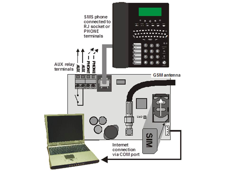
2 First time turning on the communicator
If the communicator is installed in the housing and the GSM antenna is inserted then
:a) Leg a SIM card ready. It should be pre-activated (first check that the SIM card works in a mobile phone). If a PIN code must be entered when the phone is turned on, disable the PIN function. (E.g. Nokia menu via: Menu / Settings / Security / PIN code request / off). The communicator can work with a prepaid card, but for more reliable operation use a subscription. (see 5.16)
b) Insert the SIM card into the communicator (to open the card holder, slide it slightly upwards)
c) Switch on the power supply (230V + battery). The communicator's red LED goes off within 1 minute = connection to GSM network successful.
If the LED starts flashing after a while, turn off the control panel, put the SIM card in a mobile phone and check that the network has sufficient coverage near the control panel and no PIN code is needed.
d) Close the control panel by placing the cover, the control panel should be in Service mode - if not, key *0 Service code (factory code 8080) if the alarm is disabled
e) Press 922 to measure the strength of the GSM signal.. (displayed between 1/4 to 4/4) It should be at least 2/4 for reliable operation. If the signal is too weak, try moving the unit or using a SIM card from another provider. (It is not recommended to use a high-gain or directional antenna - see 5.1)
f) If the GSM signal is sufficient, test the functioning of the communicator (for example, by calling the SIM card number and authorizing your phone) - see 3.3
If the control panel is placed near the border with another country where a foreign network can be picked up (e.g. when the signal strength fluctuates), we recommend that that the roaming setting in the SIM card is turned off to avoid high costs. Contact the provider for details.
3 User functions of the communicator
The following text describes all communicator functions. The installer could explain these functions to the user if they are applicable in a particular installation.
3.1 Making calls via the connected telephone
The communicator simulates a telephone line (including CLIP protocol) on the telephone socket:
- The telephone (Tone-only communicator - preferably the Jablotron SMS 8010 model) must be connected to the telephone socket on the communicator (or the telephone connection points).
- The telephone can be used just like a landline telephone (Factory setting).
- If the Jablotron SMS801 telephone is used, SMS messages can be sent and received in addition to calls . Missed calls are stored and displayed. A list of numbers is also available. (see also 5.10.1)
- The communicator disconnects the current call if alarm data needs to be sent.
- Some phones are sensitive to GSM signals in the immediate vicinity. If you hear interference on the line coming from the communicator's GSM signal, move the connected phone.
3.2 Listen-in and voice communication
If listen-in and voice communication is required, the SP-02 intercom should be connected to the telephone line output. The intercom can be put in parallel with any other telephone. The SP-02 works as a speakerphone which automatically answers incoming calls from numbers authorized to use this feature. The SP-02 module also has an emergency call function to a pre-programmed number. See the SP-02 manual for details on authorizing numbers and how to program the emergency call number.
3.3 Temporarily authorize a telephone keypad as a control panel.
It is possible to control the system remotely by temporarily authorizing a telephone keypad as a control panel:
a) Dial the number of the SIM card (if a phone is connected to the simulated line it will ring).
b) After 25 seconds of ringing (adjustable) the communicator will answer with a short tone.
c) Key in an appropriate access code on the phone (e.g. 8080 or 1234 if the factory setting is still in effect)
d) The telephone keypad will respond as if it were a system control panel. A tone signal will be heard indicating the status of the system: 1 tone = Enabled, 2 tones = Disabled, 3 tones = Service mode, 4 tones = wrong code used, sound of a siren = alarm
e) Now the system can be operated from the telephone keypad in the same way as a control panel, including commands beginning with * (e.g. *81 turns on the PGX output)
f) To exit this mode disconnect (if nothing happens within one minute the line is automatically disconnected)
Important:
§ Do not enter the codes too fast, Each tone needs a time to be sent (depending on the phone and the quality of the connection)
§ A landline phone can also be used (provided it is set to tone dialing)
§ The system can also be operated by a telephone connected to the simulated line. Pick up the handset and briefly press # and the phone is now a control panel. To stop put the handset on hook.
§ Phones must be authorized each time the control panel feature is used by using the previously mentioned codes. The authorization ends after each call.
3.4 SMS instructions to operate the system remotely
All incoming SMS messages are checked for instructions for the system and are executed right away. The SMS instruction must meet the following conditions: code_instruction (valid code space instruction)
Valid code = a valid code of the system (e.g. 8080, 1234 etc.)
Default instruction set: (can be changed - see 5.4
)| Instruction | Function | Explanation |
| SET | Enable | Turning the system on and off (in the same way as a control panel). |
| UNSET | Disable | If the system is already in the desired mode, nothing happens. |
| STATUS | Query status | Includes GSM signal strength, GPRS data, ARC communication (shown as MS1 and MS2). |
| MEMORY | Retrieve last action | The last operation stored in the system memory. |
| PGX ON | Turn PGX on | The PG outputs must be programmed for the function: on/off (dmv 237/247) or 2 second switching (dmv 238/248) |
| PGX OFF | Disable PGX | The PG outputs must be programmed for the function: on/off (by 237/247) or 2-second switching (by 238/248). |
| PGY ON | PGY ON | The PG outputs must be programmed for the function: on/off (dmv 237/247) or 2-second switching (dmv 238/248). |
| PGY OFF | Disable PGY | The PG outputs must be programmed for the function: on/off (dmv 237/247) or 2-second switching (dmv 238/248). |
| AUX ON | Turns AUX on | Switches the AUX socket on the communicator on or off |
| AUX OFF | Turns AUX off | Switches the AUX socket on the communicator on or off |
| CREDIT | Request SIM card credit | Must be initialized by SMS before it can work see: 5.16 |
Example: sending "code SET" (valid code space SET) will turn the system on (if the system is already on, nothing will change)
Note:
§ execution of the instruction is confirmed by an SMS response
§ the instructions are not case sensitive and only ASCII characters are allowed
§ only one instruction can be sent in an SMS
§ the enable/disable instruction after a service code is executed only if the enable/disable option with service code is enabled. (this prevents unauthorized enabling and disabling by an installer)
§ An SMS instruction can also be sent to the system with a telephone connected to the simulated telephone output on the communicator (e.g. SMS8010) - send to telephone number 001 (free of charge)
§ If there is any other text in the SMS message, which is not separated by %, the instruction will not be executed.
§ If you are sending and message and you are not sure whether or not other text will be automatically added (e.g. if you are using via an SMS internet server) send the instruction in the following way:
instruction%%
3.5 Free operation of the system through missed calls from preprogrammed numbers
A limited number of instructions can be performed remotely by calling the system from an authorized phone and making the call terminate before the system picks up the line. In this way the system can be operated free of charge with a limited number of functions. It is possible to authorize numbers stored in memory M1 to M8 (also used as warning numbers see 4).
To authorize a phone number place * after the number followed by one digit (1,2,3,8 or 9) - See note in section 4.
If a call is made by that number the communicator will generate "* digit" after the first ring. (As if manually keyed in on the control panel). This free control of the system with unanswered calls can include the following functions according to which digit is after the * in memory:
*1 Enable complete system (= ABC button on control panel)
*2 Enable section A (= A button)*
*3 Enable section A and B or B (= B button)*
*8 PGX on for 2 seconds. (If the PGX is programmed for the pulse function)
*9 PGY on for 2 seconds. (If the PGY is programmed for the pulse function)
Notes:
§ If the phone rings with number lock cannot be used to operate the system in this way
§ If the call is terminated before the dialer answers, this function is free.
§ A phone that has this free function can also fully operate the system once the communicator has picked up and a valid code has been entered (see 3.3). Let the phone ring until the communicator picks up the line.
§ If the number programmed for free control does not need to receive system reports, disable reports for this number (see 5.3).
§ Enabling with *1, *2 and *3 only works if this is activated in the control panel.
4 Reporting to phone
The communicator can report system actions by SMS and/or calling numbers with a sound signal. Reports can be sent to up to 8 numbers.
The most common reports are already set up from the factory, you only need to program the numbers in the place that contains the correct settings. If required, other operations can also be added or deleted. (see 5.3)
Default settings for numbers M1 to M8
| M | Reports |
| 1 | Alarms and errors via SMS |
| 2 | |
| 3 | Alarm and error by SMS + call (when you answer you will hear a siren) |
| 4 | |
| 5 | Alarm via SMS + calling, enable and disable and errors via SMS only |
| 6 | |
| 7 | Alarm by ringing (when you answer you will hear a siren) |
| 8 | Technical error SMS (e.g. for an installer) |
To program a phone number in one of the memory locations M, key in the following sequence when the system is in service mode: 81 M xxx...x *0
Where:
M memory location 1 through 8
xxx....x phone number (up to 20 digits)
Example: By keying 81 5 777 777 777 *0 the number 777777777 will be stored in memory location 5 (Alarm via SMS + dialing, enable and disable and errors via SMS only)
To remove and number from location M key: 81 M *0
Notes:
§ entering *9 before the number generates a "+" for programming an international number
§ If desired, actions can be sent to a connected SMS phone (SMS8010), program number 001 in the memory.
§ SMS report consists of: Installation name, action name, number and name of origin (device or code), date and time.
Example: "Report of your Alarm: enabled 47: code Time 01.08. 11:27".
§ If other actions or text should be reported to a specific number, change the setting in the communicator (see 5.3 and 5.4)
§ When entering phone numbers, if you enter *7 after the last digit of the phone number (the * is also stored) and then add one more digit (1,2,3,8 or 9), this number can call the system. The system then responds as if "* digit" was keyed in after the first ring. In other words, as if it was manually keyed in on the control panel. - see section 3.5. Example: entering 81 5 777 777 777 *79 *0 has the number 777777777 can turn on the PGY output for 2 seconds just by calling the system and ringing once. The system then responds as if *9 was keyed on the control panel. This can be used, for example, to open an automatic door or gate.
4.1 Programming
The easiest way of programming is by means of a PC with the ComLink software or via the Internet on the page: www.gsmlink.cz
Programming is also possible on the control panel:
§ The control panel must be in service mode, if not key in *0 Service code (default: 8080) while the system is switched off.
§ Key in the relevant programming sequences - see table below.
§ To exit service mode press the # key
5.1 Measuring GSM signal strength
A good quality GSM signal is required for proper functioning of the communicator. With the sequence 922 a signal measurement of the GSM network is done. The control panel then shows how strong the GSM signal is with the value ¼ to 4/4 and will repeat every second (beeps at each measurement) In this mode a suitable location of the central office are found (or from the GSM antenna). Press # to stop the measurements. The signal should indicate at least 2/4. In locations with low signal, we recommend trying to use another GSM sim card.
Warning: It is not recommended to use and high-gain or a directional GSM antenna for better signal. This way the communicator will only communicate with one GSM base station and the communication will not be stable. Also note that the distance from the antenna to a GSM base station should not exceed 30 km (even if the signal is strong enough) Time delays in the GSM network can lead to errors in data transmission. (e.g. the timing of the CID protocol).
5.2 Programming telephone numbers for reporting to telephones
See chapter 4.
5.3 Selection of reports to be sent to telephones
The default list of reported calls and their position in the memory M1 to M8 can be changed as follows.
§ It is possible to select whether a report is sent by SMS only, by call only or by SMS followed by a call.
§ Each report has its own default SMS text. These texts can be customized (see 5.4). The sound of the siren during a call cannot be adjusted (e.g. an alarm situation is indicated by a siren when you pick up the phone).
5.3.1 Setting actions to be forwarded to a specific number via SMS.
To link actions to reports via SMS key: 82 ec M x
Where:
ec code of the action 01 to 32 (see table above)
Phone number at memory location 1 to 8
0
= no SMS report, 1 = yes SMS report
Example: If 82 03 8 1 is programmed and a smoke alarm goes off (event 03 in the table), the communicator will send an SMS report to the number at memory location M8.
.3.2 Setting up operations to be forwarded to a specific number via a call
To link operations to reports via a call key: 83 ec M x
Where:
ec code of the operation 01 to 32 (see table above)
Phone number at memory location 1 to 8
0
= no call, 1 = call does
Example: if 82 03 1 1 is programmed and a smoke alarm goes off (event 03 in the table), the communicator will send a call to the number at memory location M1, if the call is accepted a siren will be heard.
Notes:
§ Alarm via call is used the dung as an audio alert to let the user read the detailed SMS report.
§ If both SMS and call are used the SMS will be sent first, then the call. Reporting to an ARC goes before anything else if it is active. (see 7.1 )
5.4 Changing SMS text
The communicator contains several pieces of text to generate an SMS report as well as an SMS instruction set. These texts cannot be changed on the control panel, but can be changed with the ComLink software, via the Internet(www.gsmlink.cz) or by sending the following SMS instruction: code_TXT_n,text,n,text,......n,text
Where:
code is a valid code (e.g. default codes 8080, 1234)
_ is a space
TXT Instruction to change text
n Text number (0 to 611 see next table)
, comma (or end)
text The new text (max. 30 characters) which will overwrite the old text. It is not allowed to use a comma or an ending in the new text, a space is allowed.
Notes:
- A single TXT instruction can change multiple texts (limited by the maximum length of a single SMS)
- The communicator is not case sensitive and it is recommended to use only English ASCII characters. (some networks do not accept non-English characters)
- The communicator creates an SMS with 5 parts: Installation name, description operation, source (code or device) number (01 to 50), source name, time and date.
- The maximum length of an ASCII SMS is 160 characters (70 characters for national characters). If this length is exceeded, the communicator will divide the report over multiple SMS messages.
Examples: if the service code is 8080 then the following instruction: 8080 TXT 20,Remote control Peter,21,Remote control Karin will be the description (name) of the remote controls at addresses 20 and 21.
8080 TXT 605,heating on,606,heating off changes the 2 instructions used to switch the heating using the PGX output (This must be programmed den as on/off.
5.5 Setting up reporting to a telephone
Reports can be set up in the following way:
800 All SMS and call reporting disabled
All SMS and call reporting enabled
802 All reporting enabled except reporting of turning on and off by users 41 to 50 (including codes, cards and remote controls). This allows to disable reporting to recipients of reporting (users, boss etc.).